 Damien Douxchamps, Co-Founder
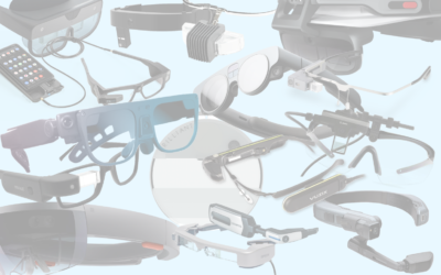
Eye box: the most critical spec of smartglasses that no one is talking about
The eye box is the secret behind good AR UX. Discover what it is and how to take full advantage of this hidden smartglasses spec
Introducing camera calibration and its importance in high-accuracy augmented reality
In the world of smartglasses, delivering a seamless augmented reality (AR) experience is paramount: it is the difference between a gimmick UI floating in the air and true augmentation registered with the real world. At the heart of this experience lies a fundamental process that often goes unnoticed but is crucial for AR’s success: camera calibration. In this article, I will take a closer look at the art and science of camera calibration for smart glasses and how it plays a pivotal role in enhancing your AR adventures when using Augumenta’s SDK.
Our eyes are responsible for 80% of our sensory input. Smartglasses are no different: their camera(s) is the principal sensor responsible for object detection, interaction, positioning, among others. In other words, the camera is responsible for most of the 3D sensing in smartglasses. But how can two-dimensional images be used to obtain 3D data? While computer vision has changed dramatically in the last 20 years, the algorithms analyzing the 2D image still need to understand how the 3D world was projected onto the camera’s image in order to, in turn, produce their own 3D augmented objects and interaction. Obtaining the parameters of this projection is the task of geometric camera calibration.
It should be noted that most computer vision libraries like OpenCV provide their own camera calibration tools. From the developer point of view one can consider this problem “solved”, which means few will actually think deeply about calibration, which is a pity since it is one cornerstone on which most of the subsequent processing depends on. Many AR toolboxes can also auto-calibrate the camera, but this is unfortunately not as accurate as a full calibration process. Given our industrial customers that sometimes require precise positioning, at Augumenta we only use full hardcore camera calibration.
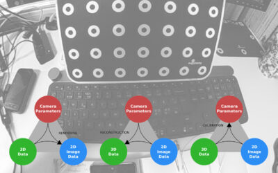
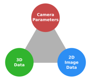
Camera calibration is one corner of the “vision triangle”, the other two corners being 3D data and 2D image data:
If you know any two corners of the triangle, then there is a way to find the third one. For example, if the camera is calibrated and 3D data is available, then 2D data can be generated. This is the familiar process called “rendering”, aka computer generated images (CGI). This is the universe of Pixar and programs like Blender:
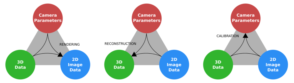
If the camera is calibrated and 2D image data is known, then it is possible to reconstruct 3D coordinates and position objects in space, for example for AR purposes. Examples include AR markers (like our SmartMarkers) and stereovision (what your eyes are doing right now!)
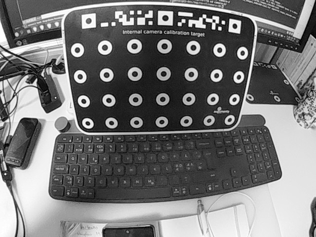
Finally, if both the image 2D coordinates and the 3D coordinates of points are known, then we can calibrate the camera. Typically this is done by taking pictures of a known calibration object and in that image detect special “fiducial” points of known 3D coordinates. Armed with these pairs of 2D and 3D points the parameters of the camera can be calculated. At the minimum the camera’s focal length is required, but good camera calibration will go well beyond that. Wide-angle lenses are important for interactive AR but unfortunately can show strong “fisheye” distorsions (wide angle lenses without significant fisheye effects are complex, heavy and expensive to build, check a Nikon lens catalog to find out…) Estimating and correcting these effects will thus be quite important in our AR applications. To achieve this the camera model we use at Augumenta contains more than 20 parameters!
At this point you’re probably thinking “This is way too complicated, I’ll get someone to do this for me”. And I wholeheartedly agree! This is why our SDK contains calibration data for every smartglasses we can get our hands on. Best of all this is transparent for the developer as the right calibration data for your smartglasses is automatically used for SmartMarker detection, gesture recognition and interactive panel interaction and rendering (SmartPanel)
For this blog post, I dug into our calibration data vault and discovered that we’ve snapped over 6000 special images and calibrated over 150 devices throughout the years, including some nifty Time-of-Flight (ToF) 3D cameras. We do all of this so you don’t have to. It’s all about keeping things simple and hassle-free for our customers. After all, why offer an SDK or productivity apps if they don’t make your life easier?
The latest additions to our list of supported and calibrated smartglasses models are the Moverio BT45CS and the Metalense from our friends at Epson and P&C.
Do you have a smartglasses project that must run on multiple devices seamlessly? Or an application that requires high accuracy measurements? Get in touch!
The eye box is the secret behind good AR UX. Discover what it is and how to take full advantage of this hidden smartglasses spec
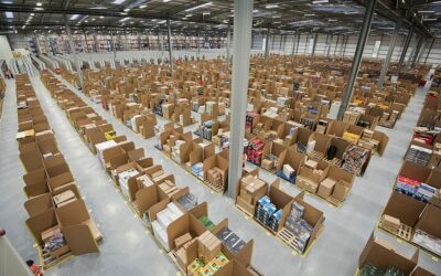
How hundreds of millions can be saved every year by large logistics operations thanks to smartglasses and SmartMarkers.
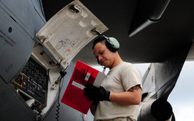
How millions can be saved every year by introducing SmartPanel and smartglasses to reduce airframe weight, shorten idle time and shrink ground crews.
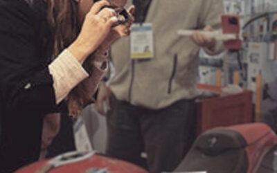
Standard QR codes are poor candidates for professional smartglasses use cases as they were designed for hand-held scanners, not head-mounted cameras. What you can do about it?